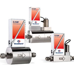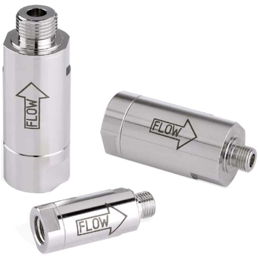

IN-LINE Filters for Gas
Inherent to its construction, a thermal mass flow meter or controller for gases is sensitive to contamination. To increase the MTBF (Mean Time Between Failure) it is important to make sure that the gas entering the instrument is clean. The IN-LINE Filter Assembly, screwed into the inlet of the instrument, provides this service. It contains a 316L sintered metal filter cartridge that is suitable for general purpose filtration and can be cleaned with a suitable solvent. If the gas contains a large particulate content, we advise the use of a pre-filter.
Description
- Filters for Mass Flow Meters and Controllers
- For increasing the MTBF (Mean Time Between Failure)
- contains a 316L sintered metal filter cartridge
- Housing: AISI 316
- O-rings: Viton; optional EPDM and FFKM (Kalrez)
IN-LINE Filters Selection
Choose low-flow or medium-flow style IN-LINE filters for instruments with 1/4” female thread at the inlet. The high-flow filter is suitable for mounting into instruments with 1/2” female thread. The ultra-low-flow filters have 1/8″ connections. In principle, select finest porosity with low ΔP. Preferably, ΔP is not higher than 250 to 500 mbar, and porosity is not bigger than 5 μm. The ΔP across the IN-LINE filter can be calculated with the help of our online calculation tool FLUIDAT.
Bronkhorst IN-LINE Filters Dimensions

| Model | A | B | C | D | G | Span 1 | Span 2 |
|---|---|---|---|---|---|---|---|
|
M-410/M-420 |
53 |
89 |
10 |
ø 24 |
1/8″ |
20 |
20 |
|
M-411/M-421 |
53 |
91 |
10 |
ø 24 |
1⁄4″ |
20 |
20 |
|
M-412/M-422 |
70 |
106 |
10 |
ø 35 |
1⁄4″ |
30 |
32 |
|
M-413/M-423 |
80 |
129 |
14 |
ø 35 |
1⁄2″ |
30 |
32 |
Pressure Drop
The approximate pressure drop across a filter assembly can be calculated as follows:
| Stylett | Model no. | Average porosity | Type / area | Connections in / out |
|---|---|---|---|---|
|
Ultra-low-flow |
M-410-13/M-420-13 |
0.5 μm |
316L / 2.5 cm2 |
1/8” female / 1/8” male |
|
M-410-16/M-420-16 |
2 μm |
316L / 2.5 cm2 |
1/8” female / 1/8” male |
|
|
M-410-18/M-420-18 |
7 μm |
316L / 2.5 cm2 |
1/8” female / 1/8” male |
|
|
M-410-20/M-420-20 |
15 μm |
316L / 2.5 cm2 |
1/8” female / 1/8” male |
|
|
Low-flow |
M-411-13/M-421-13 |
0.5 μm |
316L / 2.5 cm2 |
1⁄4” female / 1⁄4” male |
|
M-411-16/M-421-16 |
2 μm |
316L / 2.5 cm2 |
1⁄4” female / 1⁄4” male |
|
|
M-411-18/M-421-18 |
7 μm |
316L / 2.5 cm2 |
1⁄4” female / 1⁄4” male |
|
|
M-411-20/M-421-20 |
15 μm |
316L / 2.5 cm2 |
1⁄4” female / 1⁄4” male |
|
|
Medium-flow |
M-412-16/M-422-16 |
2 μm |
316L / 5 cm2 |
1⁄4” female / 1⁄4” male |
|
M-412-17/M-422-17 |
5 μm |
316L / 5 cm2 |
1⁄4” female / 1⁄4” male |
|
|
M-412-19/M-422-19 |
10 μm |
316L / 5 cm2 |
1⁄4” female / 1⁄4” male |
|
|
M-412-21/M-422-21 |
20 μm |
316L / 5 cm2 |
1⁄4” female / 1⁄4” male |
|
|
High-flow |
M-413-16/M-423-16 |
2 μm |
316L / 5 cm2 |
1⁄2” female / 1⁄2” male |
|
M-413-17/M-423-17 |
5 μm |
316L / 5 cm2 |
1⁄2” female / 1⁄2” male |
|
|
M-413-19/M-423-19 |
10 μm |
316L / 5 cm2 |
1⁄2” female / 1⁄2” male |
|
|
M-413-21/M-423-21 |
20 μm |
316L / 5 cm2 |
1⁄2” female / 1⁄2” male |
|
|
M-413-22/M-423-22 |
40 μm |
316L / 5 cm2 |
1⁄2” female / 1⁄2” male |
Example
Flow 80 ln/min air, pressure 5 bara, filter selected: M-422-17 (5 μm).
At P1 = 1 bara, ∆P across filter = 389 mbar (see second graph on the next page).
At P1 = 5 bara, ∆P = 389 = 78 mbar. 5
For other gases than air the pressure drop is difficult to calculate, because the total pressure drop is built up from both laminar and turbulent pressure losses. Therefore, use the Filter Calculations routine on Fluidat or contact us regarding exact pressure losses, if so required.