Combustion Measurement using Thermal Mass Flowmeters

- Accurate combustion measurement, including both airflow and fuel flow, is essential for improving efficiency, optimizing production, ensuring safety, and meeting environmental compliance requirements.
- Various control systems manage the air-to-fuel ratio in combustion, ranging from basic mechanical linkages to advanced fully metered systems using real-time mass flow data for precise adjustments.
- Challenges in combustion flow measurement include large ducts, low-density gases, limited straight pipe runs, and high temperatures, thus requiring specialized technologies like thermal mass flowmeters, multipoint sensors, and custom solutions for stack emissions and sampling systems.
Combustion is an essential part of many industrial processes, and it’s valuable to accurately measure the mass of combustion airflow and the mass of fuel. Industrial equipment and processes that utilize combustion include: Boilers, Process Heaters, Kilns, Furnaces, Thermal Oxidizers, Combustors, Flare, Ovens, Engines, Dryers, and others. It would be extremely difficult to find an industrial business that isn’t using combustion as part of their process. To maximize productivity and efficiency, combustion measurement is critical for collecting insight about your combustion process.
What’s the Purpose of Combustion Measurement?
Combustion is a chemical process where a fuel is combined with oxygen to produce energy. During this reaction, control of the air/fuel ratio has a direct impact on efficiency as well as the production of combustion byproducts such as NOx and SOx.
Reasons why Combustion Measurement is Beneficial
- Better efficiency = less money wasted: Fuel is a significant expense for an industrial business. And even a percent or two better in combustion efficiency can result in hundreds of thousands of dollars in savings.
- Environmental Reporting: The EPA, Air Quality Districts, and other agencies may require environmental reporting of CO2 and other emissions to ensure compliance. Failure to comply can result in punishments of fines and even plant shutdowns.
- Environmental Pollution Control: The optimal air/fuel ratio for combustion efficiency might not be the same as the optimal ratio to minimize NOx and/or SOx emissions. Good control over combustion air and fuel ratios allows plant operators to fine tune their process at any time. In doing so, that the plant can stay at or below permitted emissions targets.
- Safety: Measuring the flow of air to a combustion process can help reduce the chance of an explosion. If fuel is flowing with no airflow a dangerous situation can quickly develop. A low flow trip point on the airflow can be used to trigger an emergency shut off for the fuel flow.
- Production/Process Optimization: Quick and precise control over combustion can help a plant’s process work faster and more reliably. This often results in measurable production increases.
This graph displays the changes of combustion byproducts vs. changes in excess air and the prices control necessary to balance all factors.

How is the Air: Fuel Ratio Controlled?
There are a few different methods that combustion ratios are controlled. This section won’t cover every option, but will highlight 4 of the most common:
Single Point Positioning System
The Single Point Positioning System uses a jackshaft controlled by a master drive unit to mechanically link the fuel valves and air damper. This system does not use flowmeters to precisely control the air fuel ratio but rather utilizes annual boiler tuning services to set the ratio and that is only optimized for a single load condition.
Parallel Positioning System
The Parallel Positioning System is an alternative method that allows for independent control of the fuel valve and air damper. In this system the control signal is given to the fuel valve and the airflow actuator with manual air/fuel ratios set for a range of operating loads. This system is far better than a single point positioning system but still doesn’t make the small adjustments needed to truly optimize your combustion control.
O2 Trim System
An O2 Trim System is one way to make those small adjustments. This system monitors the unburnt Oxygen composition with an analyzer in the stack to make automatic adjustments to the air/fuel ratio. The downside to these systems is the delay (minutes) caused by the amount of time the analyzer needs to take a measurement.

Fully Metered Control System
A Fully Metered Control System offers a real time, responsive combustion control system. This system measures the mass flow of both the fuel flow and the airflow. Then operators can make independent adjustments to the fuel valve and air damper or VFD on the blower motor. These systems easily offer the best results but have been avoided historically because of the great difficulty with measuring airflow in larger ducts.
Why has Combustion Measurement been Avoided for so Long?
Large Ducts with Limited Straight Run
Combustion air duct can be very large in comparison to the fuel piping. This is because Air needs to be supplied at roughly a 10:1 ratio when using natural gas as the fuel for example. Another factor contributing to the large duct size is that most of the “air” flowing through the duct is inert Nitrogen. As a result, only the 21% that is Oxygen participates in the chemical reaction.
Not only can these combustion airflow ducts be large, but they rarely have more than 5-6 diameters of straight run. The lack of straight run does not allow for a single point measurement to be accurate. Multipoint systems and/or flow straighteners are useful, but they can be expensive, complicated, or require additional engineering.
Low Density Gas Generates a Very Low DP
One of the oldest and most common measurement technologies for flow is a differential pressure transmitter along with a flow element. For example, an orifice plate, flow nozzle, venturi, or pitot. Since air is a low-density fluid, the differential pressure arising from these flow elements is low at low velocity.
Often, DPs between 0.5″ and 1″ W.C. at max flow are common. This is a challenge for many DP transmitter manufacturers who have a 4″ W.C. transducer as their smallest span. In addition, flow rate is proportional to the square root of differential pressure rather than directly proportional to the square root of differential pressure. This limits turndown to about 4 to 1. Although it may be acceptable for normal operating flow, it would not be acceptable for use as a low flow trip point which is set to 10% of the max flow or lower.

Duct Modifications are Expensive
Single point technologies are not practical due to the limited straight run. Thus, an expensive venturi might be fabricated or a duct section replaced with a pitot array and flow conditioning assembly. These can be effective solutions for some processes. However, it can easily turn a simple measurement addition into a full-scale capital project with cranes, engineering hours, and a plant shutdown.
Thermal Mass Flowmeter Technology
Thermal mass flowmeters, with the correct features and multipoint accessories, are a great choice for nearly all gas flow measurements related to combustion measurement. There are several reasons for this, but the three most prominent are as follows:
Mass Flow Measurement – Thermal Mass Flowmeters have a unique operating principle that does not require external temperature or pressure compensation to generate an accurate mass flow value. Furthermore, the mass determines the air to fuel ratio. Therefore, it is important to have a mass flow output for fuel and airflow measurements.
Low Flow Sensitivity, High Turndowns – Thermal Mass Flowmeters offer a 100 to 1 turndown as standard. This is more than enough for all combustion measurements. However, any technology should be capable of at least a 10 to 1 turndown. This will account for the full range of operation including start up conditions.
Accurate and Repeatable – Thermal Mass Flowmeters typically have an accuracy between 1 and 5% depending on the amount of turndown, and a repeatability of 0.2%. These flowmeters would not be considered “custody transfer meters.” However, they offer great accuracy and repeatability for all the control, monitoring, and reporting measurements.
EPI’s Flow Averaging Tube for Combustion Measurement
The only downside of thermal mass technology is that it is a single point measurement, which require fully developed flow profiles to be accurate. Some manufacturers, for example EPI, offer multipoint solutions with multiple sensors along an insertion probe. However, those have a limit of 3 or 4 sensing points. EPI’s patented Flow Averaging Tube allows for dozens of sensing points to average together along the length of a probe like a pitot tube, but without the DP transmitter limitations.
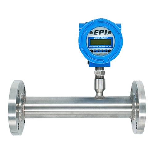
**EPI’s 9000 series transmitter with Flow Averaging Tube

By using a thermal mass transmitter instead of a differential pressure transmitter, you can measure mass flow of the combustion air without needing temperature compensation. This provides great turndowns without concerns for large accuracy uncertainties.
Combustion Measurement for Environmental Compliance

These types of flow measurements are an important step towards more effective control of industrial combustion processes. But they also play a critical role with satisfying various environmental reporting obligations. Analyzers, which determine the concentration of pollutants, are used alongside flowmeters to determine the total mass of emissions over time in continuous emissions monitoring systems. These measurements are critical for process management. Furthermore, failure to report accurate data to environmental agencies can result in fines and even force shutdowns. These flue gas measurements occur in the large diameter stacks venting the byproducts of combustion to the atmosphere.
Challenges of Stack Flow Measurements
- High Temperature – If the combustion process does not have any type of heat recovery system, the flue gas will be hot (650 to 1,000 F).
- Large Diameter with Limited Straight Run – Stacks can range in size from a few, up to many, feet in diameter. This large size along with limitations in straight run can result in an irregular flow profile.
- Limited Installation Options – For installation and maintenance purposes, the flowmeter requires installation where an access point already exists.
Common technologies for measuring stack flow include Thermal Mass Flowmeters, Pitot Tubes with DP transmitters, Ultrasonic Flow Meters, as well as Tracer Gas Injection Methods. All four of these technologies can provide an acceptable measurement. However, it’s important to consider “what does it take to make them work, and at what cost?”

EPI’s Solution
EPI manufactures a special high temperature multipoint solution. This design utilizes multiple single point probes or multiple multipoint probes, depending on stack geometry and available straight run. These sensors have a max temperature of 977˚F and also offer an accurate flow measurement with a simple insertion style device. Other devices might struggle with limited turndowns, expensive annual maintenance, as well as expensive stack modifications.
Measuring Sample Lines

Many analyzers also rely on flow measurements leading into or within the stack gas sampling cabinets. This measurement is challenging for many technologies due to high temperatures, small line size (1/4″ or 3/8″ typically), and low flowrate. EPI offers a special “Axial Thermal Mass Flowmeter” specifically for high temp/low flow applications with small line sizes. The geometry inside our flow body delivers a more reliable flow profile over the sensor. As a result, the output is more stable and reliable.
**Photograph of the internal section of EPI’s Axial Flowmeter for low flow, high temperature gases.
Summary of Different Flow Measurements for Combustion Measurement
Combustion Measurement of Airflow – is a challenging measurement due to the large duct sizes. However, it is a measurement that is critical to optimize your combustion process. Fully metered control systems are the only option for real time control of the air/fuel ratio at all operating loads including start-up.
Low flow trip point – This airflow measurement ensures there is a minimum amount of air flowing or the fuel gas valve is shut off to prevent a possible explosion. This flowrate is typically 10% of the max flow or lower.
Fuel Gas – is a critical flow measurement for effective combustion control. It’s also a requirement for many environmental reporting values including CO2. Some air quality districts might even require non-resettable totalizers as part of their enforcement.
Stack flow rate – Stack flow measurement is a necessary part of the analyzer system for monitoring stack/flue gas emissions when using CEMs.
Flue gas recirculation – In some systems, portions of flue gas recirculate and mix with the combustion air. This measurement has the same challenges as combustion air but now at high temperature.
Sampling system flowrates (EPI’s axial flowmeter) – Analyzers often need a reliable flow measurement of the gas entering the sampling systems. This application can often be at high temperature, low flow, and in small line sizes.
**Diagram of the internal section of EPI’s Axial Flowmeter for low flow, high temperature gases.

Combustion Measurement of Air – EPI 9000 Series Thermal Mass Flowmeter with Flow Averaging Tube

- Direct Mass Flow Measurement without additional temperature or pressure sensors.
- Turndown Ratios as high as 100:1.
- Multipoint insertion probe for easy and low -cost installation without major duct modifications.
- EPIVAL field calibration validation feature to avoid unnecessary maintenance.
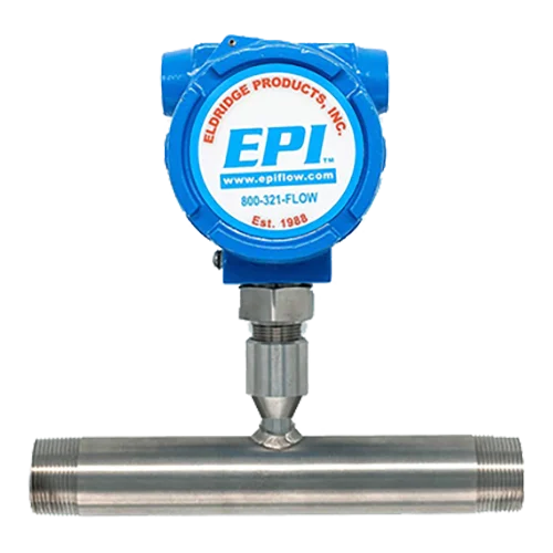
Fuel Gas – EPI 8000 Series Thermal Mass Flowmeter
Stack Flowrate / Velocity – EPI Thermal Mass Multipoint Flowmeter Solutions

- High Temp Flue Gas Applications up to 977˚F (525˚C).
- Turndown Ratios as high as 100:1.
- Multipoint insertion probe for easy/low-cost installation without major duct modifications.
- Remote electronics for a safe as well as convenient interface location.
- EPIVAL field calibration validation with reporting function. Self-validate in less than 5 min.
Stack Sampling Flowrate – EPI AXIAL FLOWMETER
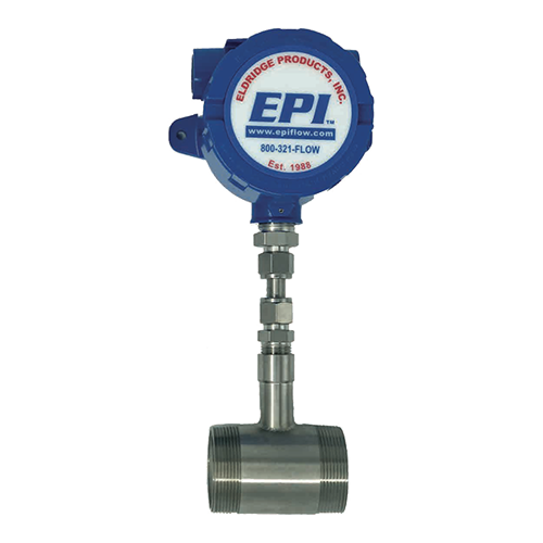
- Direct Mass Flow Measurement without additional temperature or pressure sensors.
- High Turndown Ratio.
- EPIVAL field calibration validation feature to avoid unnecessary maintenance.
- Specially designed for stack sampling and other Low Flow, High Temp applications.