How do RTD Temperature Sensors Work?
The Fundamentals of RTD temperature sensors
An RTD temperature sensor is a common device for temperature measurements in a wide range of industrial applications. In this article, we take a look at how they work, the most common types, and their advantages and disadvantages.
The acronym “RTD” stands for “Resistance Temperature Detector”. Typically, RTDs contain either platinum, nickel, or copper wires, as these materials have a positive temperature coefficient. This means that a rise in temperature results in an increased resistance – this change of resistance is then used to detect and measure temperature changes.
Platinum RTDs
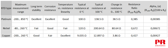
Platinum RTDs are the most common type of RTD used in industrial applications. This is because platinum has excellent corrosion resistance, excellent long-term stability, and measures a wide range of temperature, (-200…+850°C).
Nickel RTDs
Nickel RTDs are less expensive than platinum and have good corrosion resistance. However, nickel ages more rapidly over time and loses accuracy at higher temperatures. Nickel is limited to a measurement range of -80…+260°C.
Copper RTDs
Copper RTDs have the best resistance to temperature linearity of the three RTD types, and copper is a low-cost material. However, copper oxidizes at higher temperatures. Copper is limited to a measurement range of -200…+260°C.
How RTDs are constructed
Most RTDs are built in one of three ways: wire wound RTDs, coiled element RTDs, and thin film RTDs.
Wire wound RTD
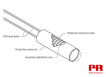
In a wire wound RTD, a resistance wire is wound around a non-conducting core, which is usually made of ceramic. The sensor maker carefully trims the length of resistance wire to achieve the specified resistance at 0°C. This is called the “R0” resistance.
Next, lead wires are attached to the resistance wire, and then a glass or ceramic coating is applied over the wire for protection. As temperature increases, the length of resistance wire increases slightly. Care must be taken in the design to ensure that the resistance wire does not twist or otherwise deform as temperature increases. This is because mechanical strain causes a change in wire resistance.
Laboratory-grade RTDs used by calibration and standards laboratories eliminate this source of error by loosely winding resistance wire around a non-conducting support structure. This type of RTD can be extremely accurate, but is fragile and not suited for most industrial applications.
Coiled element RTD

In a coiled element RTD, the resistance wire is rolled into small coils, which loosely fit into a ceramic form that is then filled with non-conductive powder. The resistance wire is free to expand and contract as temperature changes, minimizing error caused by mechanical strain. The powder increases the rate of heat transfer into the coils, thereby improving the response time. Coiled element RTDs are usually protected by a metal sheath and are used in industrial applications.
Thin film RTD

Thin film RTDs are mass-produced and cost less than the other RTD types. They are smaller, and have a faster response time than the others, which is desirable in many applications. They are made by depositing a thin pathway of platinum on a ceramic base.
The manufacturer adjusts the resistance at 0°C by opening parallel shunts in the pathway with a laser beam. The more shunts are opened, the higher is the resistance at 0°C. Thin film RTDs are not as accurate as the other types because:
- The R0 resistance cannot be adjusted as precisely as in the other types.
- The ceramic base and platinum coating have slightly different expansion rates. This creates a strain error at higher temperatures.
- Because thin film RTDs are smaller, the RTD excitation current causes a slightly higher error due to RTD self-heating.
RTD resistance ratio
The term “resistance ratio” describes the average slope of temperature vs. resistance as the RTD temperature changes from 0°C to +100°C. The expression for resistance ratio is:
(R100-R0) / R0
Where:
R100 = RTD Resistance at 100°C.
R0 = RTD Resistance at 0°C.
Resistance ratio is affected by the type and purity of the metal used to make the RTD. In general, RTDs that have a high R0 value combined with a high resistance ratio are easier to measure accurately, but other characteristics of the metal used in the resistance wire still affect the inherent accuracy of the RTD.

Platinum RTDs found in industrial applications, usually conform to the IEC 60751 standard. These RTDs have a resistance ratio of (138.5 Ω – 100 Ω) / 100 Ω = 0.385 Ω / °C. In a typical industrial application, this type of RTD is protected by inserting it into a stainless steel sheath.
Laboratory-grade RTD standards use higher purity platinum with a higher resistance ratio: (139.2 Ω – 100 Ω) / 100 Ω = 0.392 Ω / °C. At temperatures above +670°C, metal ions liberated from the stainless steel probe will contaminate the high purity platinum, changing its resistance ratio. For this reason, these RTDs are protected by a probe made of silica glass or platinum. These probe materials remain inert at high temperatures, so the RTD remains uncontaminated.
Nickel RTDs conforming to DIN 43760 have a resistance ratio of (161.7805 Ω – 100 Ω) / 100 Ω = 0.618 Ω / °C.
Nickel RTDs commonly used in the USA have a resistance ratio of (200.64 Ω – 120 Ω) / 120 Ω = 0.672 Ω / °C (shown in the graph above).
Copper RTDs[1] are available with R0 = 9.035 Ω or 100 Ω. Both types have a 0.427 resistance ratio:
(12.897 Ω – 9.035 Ω) / 9.035 Ω = 0.427 Ω / °C.
(142.7 Ω – 100 Ω) / 100 Ω = 0.427 Ω / °C.
Benefits of using nickel or copper RTDs
Nickel creates a high resistance at 0°C and has a high resistance ratio, making this sensitive RTD easy to measure. These qualities also minimize error due to lead wire resistance. For an RTD, the approximate error due to lead wire resistance is:
Lead wire resistance / (R100-R0) x 0.01
For example:
A 2-wire nickel RTD measures an air duct temperature. Each lead wire has a resistance of 0.25 Ω, for a total lead wire resistance of 0.5 Ω.
The error due to lead wire resistance can therefore be calculated as follows:
0.5 Ω / (161.78 – 100) x 0.01 = 0.81°C. This is close enough for many applications.
To compare, here are the numbers for a 2-wire platinum RTD with the same lead wire resistance:
0.5 Ω / (138.5 – 100) x 0.01 = 1.3°C.
Because a nickel RTD is so sensitive, a low-cost, low-accuracy transmitter can measure the RTD with acceptable accuracy. Nickel RTDs are found in HVAC and other price-sensitive applications.
Copper RTDs have the same thermal expansion rate and electromagnetic hysteresis as copper winding’s used in electric motors and generators. For these reasons, copper RTDs are sometimes used to measure winding temperature.
Copper also has an extremely linear temperature vs. resistance relationship. Because of this, it is possible to accurately measure a narrow temperature span without additional linearization.
For example:
A Cu100 RTD creates 100 Ω resistance at 0°C and 142.743 Ω resistance at 100°C. A linear extrapolation gives the theoretical resistance at 50°C: (R100 – R0)/2 + R0
= (142.743 – 100)/2 + 100 = 121.3715 Ω
According to published Resistance vs. Temperature tables, the RTD creates resistance of 121.3715 Ω at 50°C, so the RTD is functionally linear between 0…+100°C.
The non-linearity of copper does not become apparent unless measuring a wide span. For example, if measuring 0…+200°C, a linear extrapolation gives the theoretical resistance at 100°C as (185.675 – 100) / 2 + 100 = 142.838 Ω. According to the tables, however, the RTD resistance at 100°C is 142.743 Ω.
The difference of +0.095 Ω in°C : 0.095 Ω / 0.427 Ω per degree = an error of +0.222°C.
RTD tolerance
Most sensor builders make Platinum RTDs with accuracy levels that conform with the IEC 60751 or ASTM E1137 RTD standards.
The IEC 60751 standard defines four tolerance classes: Class AA, A, B, and C. The ASTM E1137 standard defines two tolerance grades: Grade A and B.
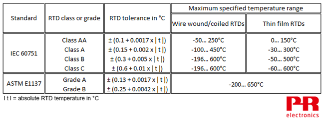
Note that IEC 60751 specifies a maximum temperature range for each class. For example, a class A sensor equipped with a coiled RTD element must maintain the specified tolerance from -100…+450°C. When operated outside this temperature range, the sensor accuracy might default to class B.
Sensors that meet ASTM E1137 grade A or grade B tolerance must maintain the specified tolerance from -200…+650°C.
This table shows the calculated tolerance for each class and grade of RTD. Notice that class C RTDs have a wide tolerance of ±6.6°C at 600°C. Most industrial applications require RTDs with Class B or better tolerance.

The following graph shows the tolerance of RTDs that conform to IEC60751. You can see that RTDs are most accurate at 0°C, and exhibit a greater error as the temperature gets hotter or colder than 0°C.

Many sensor builders offer RTDs with better than Class AA tolerance. The tolerance of these high accuracy RTDs is usually described as a fraction of class B tolerance. In the graph below, a “1/5 Class B” RTD has a tolerance of only ± (0.06 + 0.001 ǀ t ǀ) between -30…150°C. This tolerance is five times better than a class B RTD.

Callendar Van Dusen equations
The Callendar van Dusen equations describe the temperature vs. resistance relationship of industrial platinum RTDs. There are two Callendar van Dusen equations:
For temperatures < 0°C, RTD resistance at a given temperature is:
Rt = R0[1 + At + Bt² + C (t – 100) t³]
For temperatures ≥ 0°C, RTD resistance at a given temperature is:
Rt = R0(1 + At + Bt²)
Coefficients A, B, C, and α, δ, β are unique to each RTD. The following values apply to RTDs conforming to IEC 60751 and ASTM E1137 standards:
A = 3.9083 x 10⁻³
B = -5.775 x 10⁻⁷
C = -4.183 x 10⁻¹²
α = 3.85 x 10⁻³ *
β = 1.5°C
δ = 0.1086
* “α” is the “Alpha” constant. Alpha is resistance ratio/100:
α = (R100 – R0) / (100 x R0).
The alpha of a Platinum RTD that complies with IEC 60751 is:
(138.5 – 100) / (100 x 100)
= 0.00385
Nickel RTDs have an alpha of:
0.672 / 100 = 0.00672.
Copper RTDs have an alpha of:
0.427 / 100 = 0.00427.
RTD Characterization
Even high quality RTDs do not exactly match the IEC 60751 / ASTM E1137 R:T curve. To further improve measurement accuracy, a calibration lab can “characterize” an RTD. This is done by carefully measuring the RTD resistance at a few different temperatures and then using that data to derive the α, δ, β and A, B, and C coefficients.
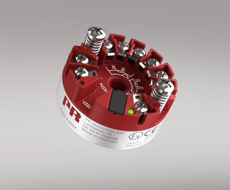
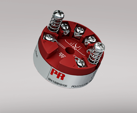
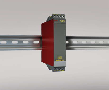
The 5437 2-wire HART temperature transmitter, the 5337 2-wire transmitter with HART protocol, and the 6337 2-wire HART transmitter can be programmed with these coefficients, precisely matching the transmitter to a characterized RTD for exceptional measurement accuracy.