

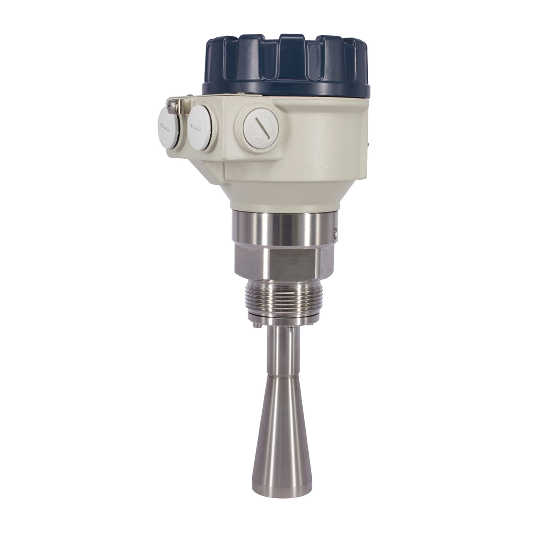
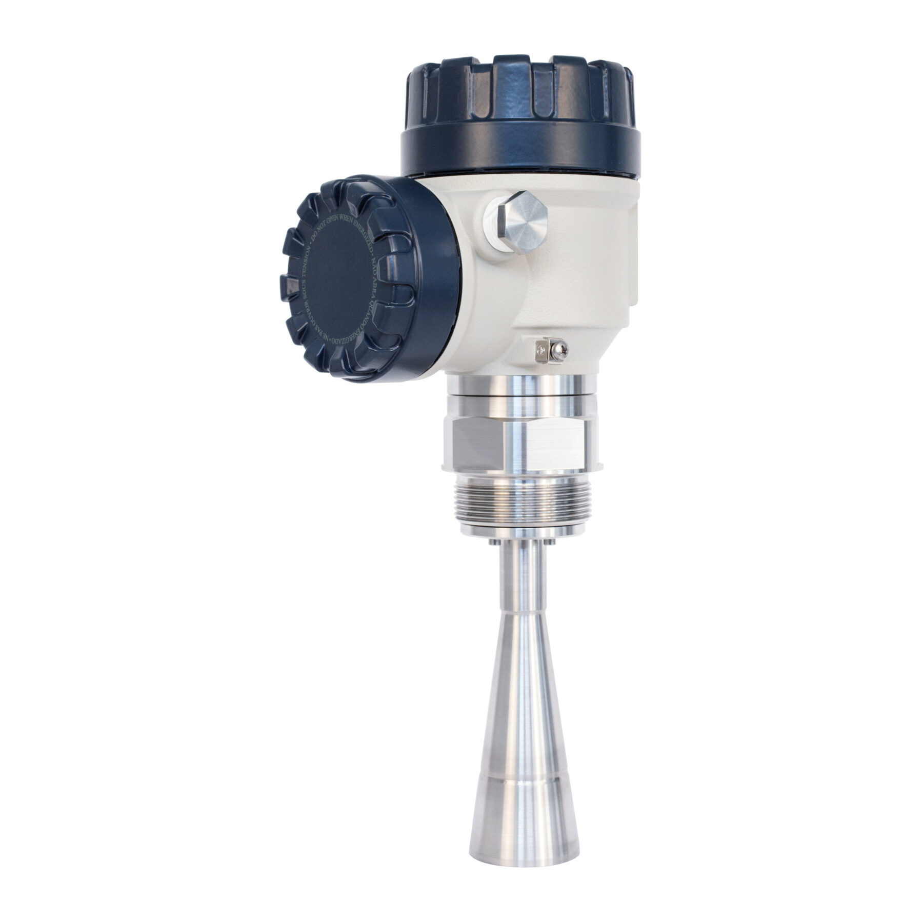
PiloTREK Compact Series, Microwave Level Transmitter
The 25 GHz (K-band) PiloTREK Compact Series Microwave / Pulse Radar Level Transmitters are regarded as the most progressive non-contact level transmitters of the industrial process automation field. The accuracy of PiloTREK Compact Series microwave level transmitters are excellent and their short and narrow antennas make their installation simple and low cost. Featuring K-band radar with ±3 mm (0.12 inch) accuracy and short dead band, these transmitters excel with its versatile housing concept lining up plastic, aluminum, and stainless steel versions.
Wide Range Antenna with Easy Programming
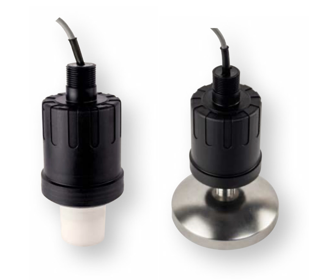
Its antenna range incorporates stainless steel horn or parabolic planar antenna and enclosed plastic tube varieties. The enclosed antenna versions can be replaced without removing the antenna enclosure from the process. Local programming of the PiloTREK Series is aided by an optional plug-in display module.
- 2-wire K-band Pulse Burst Radar
- 25 GHz frequency
- Maximum 75 feet measuring range for liquids and slurries
- ±3 mm (0.12 inch) accuracy
- Easy installation due to small antennas
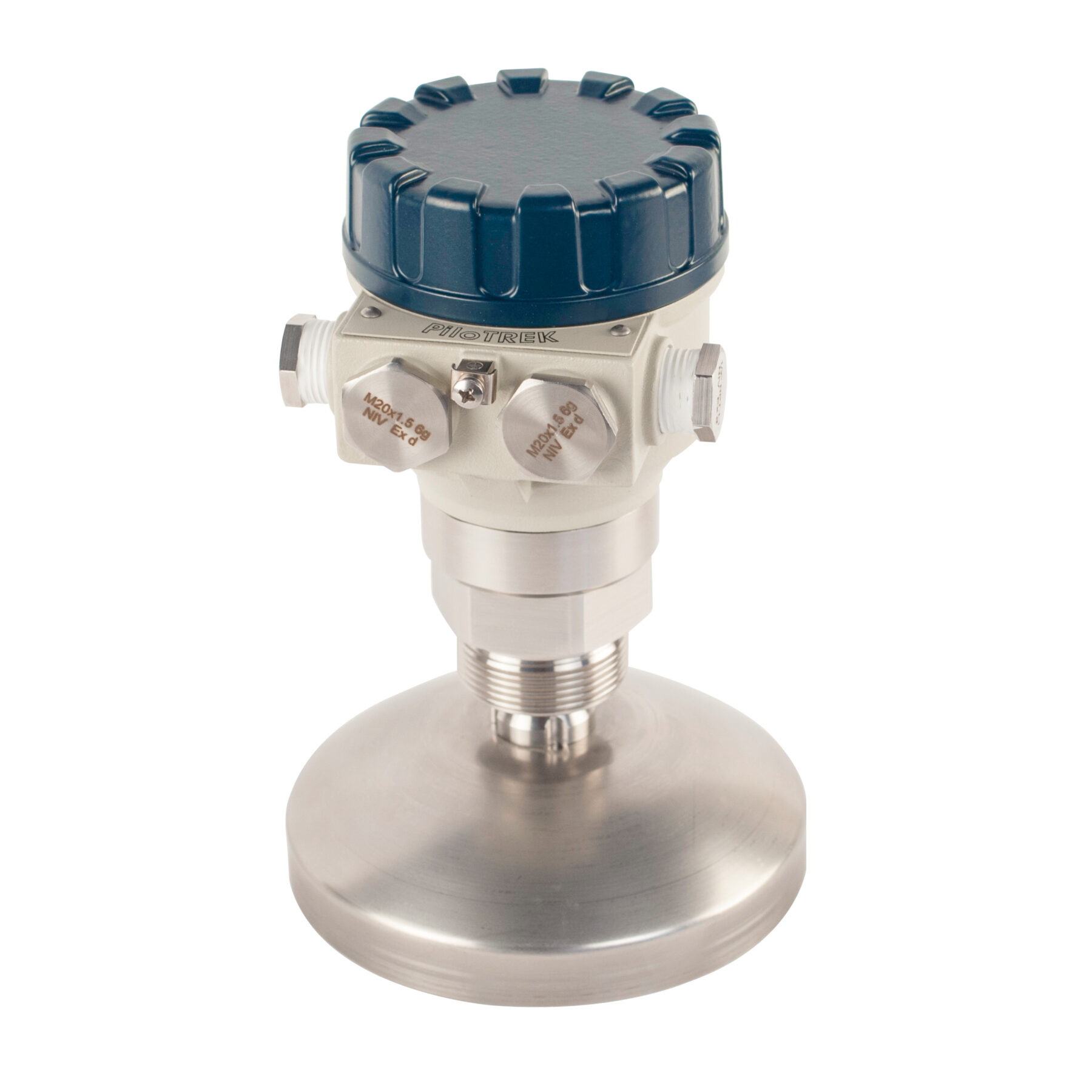
- Parabolic, horn, planar and enclosed antenna types
- IP68 rated integrated type
- Sanitary types for meeting high hygienic requirements
- High temperature version, Ex version
- Plug-in graphical display module
- FM & CSA approved
Description
- Plastic, aluminum or stainless steel housing
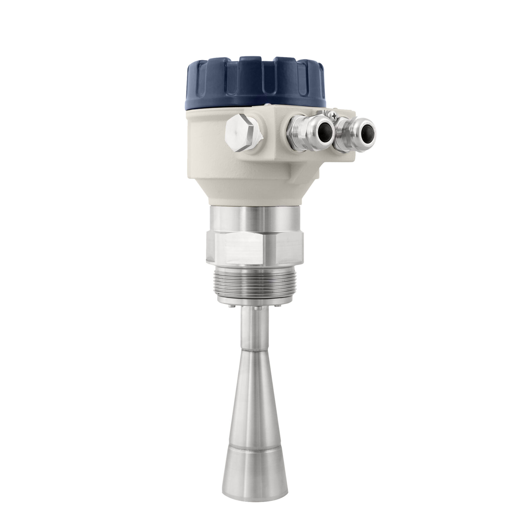
- Stainless steel parabolic, horn, or plastic-coated antenna
- Plug-in graphic display module
- High-temperature variant
- 2-wire transmitters
- 25 GHz (K-band) measuring signal
- Non-contact level metering
- Accuracy up to ±0.12 inch
- Measuring range up to 75 feet
- 99-point linearization
- Explosion-proof variants available
- 5 year warranty
Applications
- Level measurement of liquids, emulsions, slurries, and other chemicals
- Level measurement through plastic tank wall
- Agriculture
- Construction materials
- Chemical industry, for mid to large size vessels or chemical tanks
- Pharmaceutical industry
- Food and beverage
- Power plants
- Oil industry
- Water and wastewater industry
Linearly Polarized Microwave Impulses
The PiloTREK Compact Series pulse burst radar level transmitters emit linearly polarized microwave impulses. The polarization plane of the emitted impulses can be rotated fully in some PiloTREK models. The rotation of the polarization plane can minimize unwanted false reflections from disturbing objects or from the tank wall. The orientation of the polarization plane coincides with the line drawn between the cable glands.
Pulse Radar Level Transmitter Operations
The operation of the non-contact microwave level transmitters is based on the measurement of the time of flight of the microwave burst. The propagation speed of microwave impulses is practically the same in air, gases and in vacuum, independently from the process temperature and pressure, so the measured distance is not affected by the physical parameters of medium to be measured.
The level transmitter induces microwave impulses a few nanosecond long in the antenna and a part of the energy of the emitted signals is bounced (reflected) back from the measurement surface depending on the measured media. The time of flight of the reflected signal is measured and processed by the electronics, and then this is converted to distance, level or volume proportional data. The measurability of the level of a specific medium is depending on the signal strength of the reflected microwave impulses.
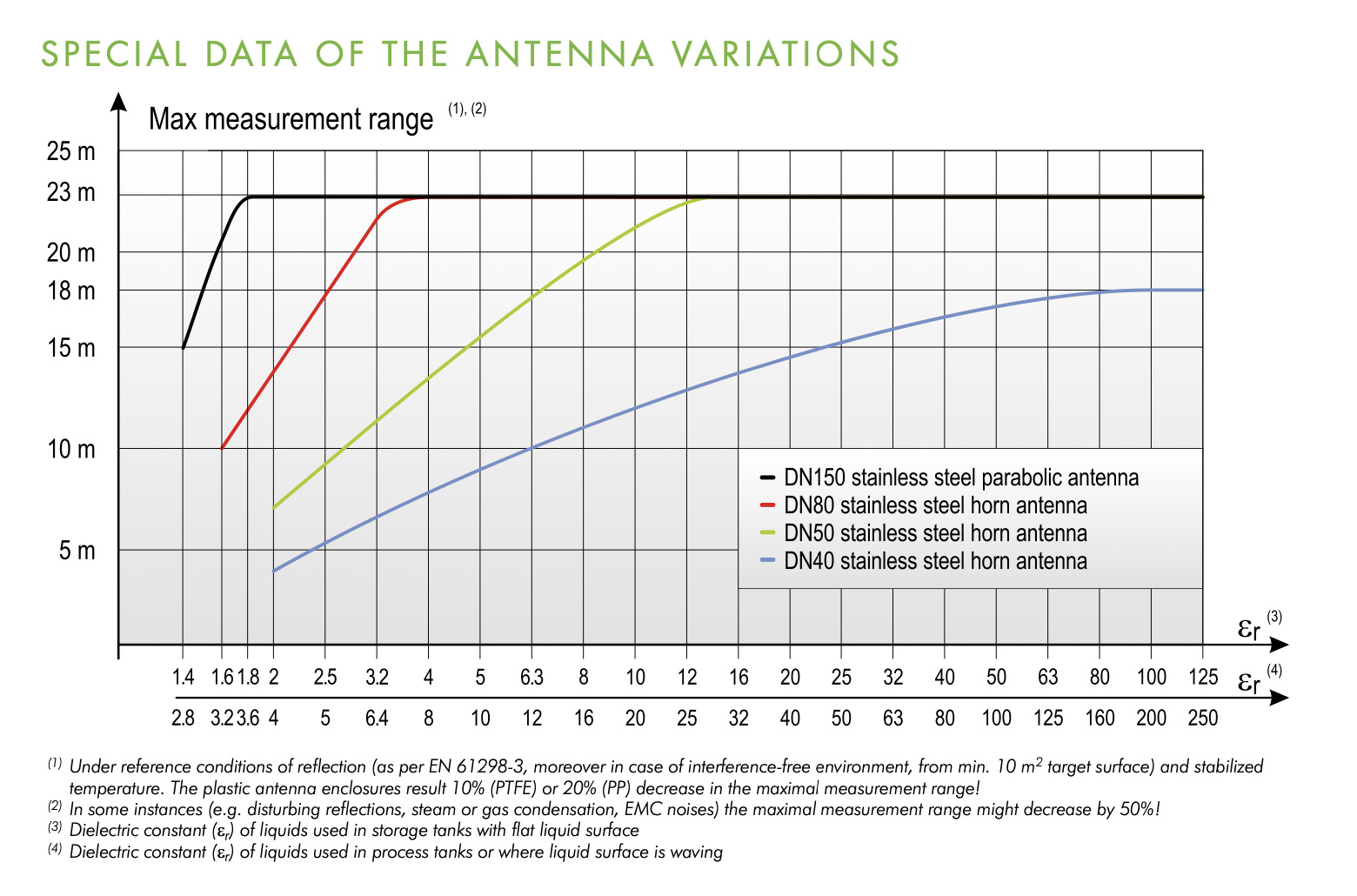
The signal strength of the reflected impulses is considerably depending on the distance to be measured, the relative dielectric constant of the measured medium and the turbulence of the surface. The relative dielectric constant (εr) of the medium should be more than 1.4 in case of parabolic design, or it should be more than 1.9 with horn antenna types.
Programming with Echo Map
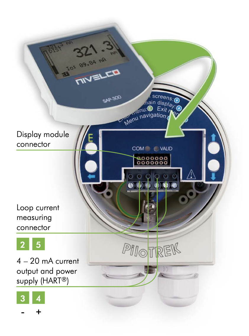
With the help of the SAP-300 plug-in display, a simplified full-parameter programming can be accomplished. The parameters of measurement and output can be set using the text-based menu system. The large LCD dot-matrix display displays the measured values in numerical and bar graph form. The Echo Map feature helps to detect false reflections and aids the optimization of the measurement configuration.
The background mapping feature provides excellent solution to ignore unwanted false reflections coming from (not-moving) disturbing objects. For this purpose the instrument needs to map the totally empty tank to create a ”background image”. Then the measurement evaluation software of PiloTREK Compact Series will automatically recognize and ignore the false reflections coming from the disturbing objects inside the tank.
PiloTREK Compact Series Microwave / Radar Level Transmitter
| Supply voltage | 20…36 V DC |
|---|---|
| Ambient temperature | −4…140°F |
| Process temperature | −22…356°F |
| Process pressure | −14.5…362.6 psig |
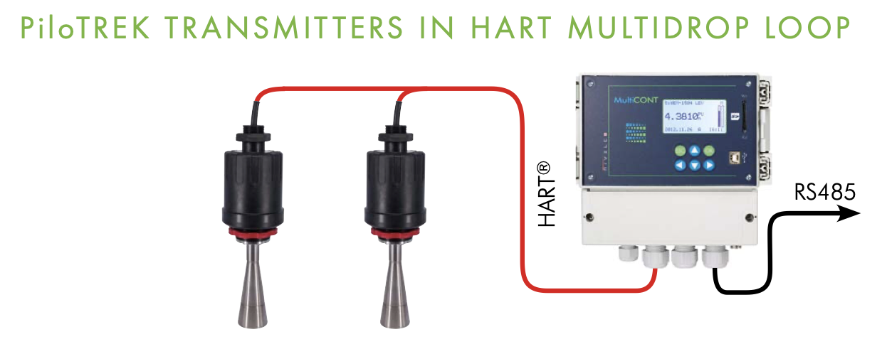
| Output | 4…20 mA + HART |
| Process connection | 1½”, 2″ or flanges or sanitary |
| Ingress protection | IP67 |
| Approvals | ATEX, IEC Ex, INMETRO |
PiloTREK Microwave Level Transmitter Model Line-Up
| PiloTREK Series | Compact Microwave Level Transmitter | ||
|---|---|---|---|
| Plastic housing | Metal housing | High temperature version | |
| Measured values | Level, Distance | ||
| Calculated values | Volume, Mass | ||
| Frequency of the measurement signal | ~25 GHz (K-band) | ||
| Measuring range | 0.6 – 75 ft (depending on the antenna type) | ||
| Linearity error(1) | <1.65 ft: ±1 in; 1.65 – 3.3 ft: ±0.6 in; 3.3 – 5 ft: ±0.4 in; 5 – 26.25 ft: ±0.12 in; >26.25 ft: ±0.04% of the measured distance | ||
| Minimal beam angle | 6° (depending on the antenna type) | ||
| Minimal εr of the medium | 1.4 (depending on the measuring range) | ||
| Resolution | 1 mm (0.04 inch) | ||
| Temperature error (as per EN 61298-3) | 0.05% FSK / 50 °F (-4°F…140°F) | ||
| Power supply | 20 V – 36 V DC | ||
| Digital communication | 4 – 20 mA + HART | ||
| Display | SAP-300 graphical display unit | ||
| Measuring frequency | 10 – 60 sec as per the application settings | ||
| Antenna diameter | 38 mm (11⁄2″), 48 mm (2″), 75 mm (3″), 148 mm (6″) | ||
| Antenna material | Horn, Parabolic: 1.4571 (316Ti) stainless steel; enclosure: PP, PTFE | Horn, Parabolic: 1.4571 (316Ti); enclosure: PTFE | |
| Process temperature | -22°F…212°F, (up to 248 °F for maximum 2 minutes) with PP antenna enclosure: maximum: 176°F | -22°F…356°F | |
| Maximal process pressure | 25 bar (363 psig) at 248°F; with plastic antenna enclosure: 3 bar (44 psig) at 77 °F |
||
| Ambient temperature | -4°F…140°F | ||
| Process connection | Threaded, Flanged or Sanitary connections | ||
| Ingress protection | IP67 | ||
| Electrical connection | 2x M20 x1.5 cable glands + internal thread for 2x 1⁄2″ NPT cable protective pipe, cable outer diameter: 0.3 – 0.5 inch, wire cross section: max. 1.5 mm2 (AWG 15) | ||
| Electrical protection | Class III | ||
| Housing material | Plastic (PBT) | Paint coated aluminum or stainless steel | |
| Sealing | Viton, EPDM | ||
| Communication certifications | R&TTE, FCC | ||
| Mass | 2.2 – 3.5 lb | Aluminium: 4.4 – 5.7 lb Stainless steel: 7.9 – 8.6 lb |
Aluminium: 6.6 – 7.9 lb Stainless steel: 8.8 – 10 lb |
*Under reference conditions of reflection and stabilized temperature
Ex Certified PiloTREK Compact Series Microwave Level Transmitters
| Plastic housing | Metal housing | High temperature version with metal housing |
||
|---|---|---|---|---|
| Ex marking | IEC Ex | Ex ia IIB T6 … T5 Ga/Gb | Ex ia IIB T6 … T4 Ga Ex ia IIIC T85°C … T110°C Da/Db Ex ta/tb IIIC T85°C … T110°C Da/Db |
Ex ia IIB T6 … T3 Ga Ex ia IIIC T85°C … T180°C Da/Db Ex ta/tb IIIC T85°C … T180°C Da/Db |
| ATEX | Ex II 1/2 G Ex ia IIB T6 … T5 Ga/Gb | Ex II 1G Ex ia IIB T6 … T4 Ga Ex II 1/2 D Ex ia IIIC T85°C … T110°C Da/Db Ex II 1/2 D Ex ta/tb IIIC T85°C … T110°C Da/Db Ex II 1/2 G Ex d [ia Ga] IIB T6 … T4 Ga/Gb |
Ex II 1G Ex ia IIB T6 … T3 Ga Ex II 1/2 D Ex ia IIIC T85°C … T180°C Da/Db Ex II 1/2 D Ex ta/tb IIIC T85°C … T180°C Da/Db Ex II 1/2 G Ex d [ia Ga] IIB T6 … T3 Ga/Gb |
|
| Intrinsically safe data | Li: 200 μH, Ci: 16 nF, Ui: 30 V, Ii: 140 mA, Pi: 1 W | |||
| Power supply | Ex ia: 20 V – 30 V DC, Ex d[ia]: 24 V – 36 V DC | |||
| Ambient temperature | -4°F…140°F | |||
| Electrical connection | 2x M20 x1.5 metal cable glands, cable outer diameter: 0.3 – 0.5 inch, wire cross section: maximum 1.5 mm2 (AWG 15) | |||


